
Of The Workings Of The Graphics Memory And Minor Skills In Branching
2002-07-01 (last edition of the initial revision)
She doth teach the torches to burn bright
It’s 10:13 in the morning, school will start at 1 o’clock so I have some spare time before I’m at it. I’ve hooked Direct Connect up on some downloads; one Bruce Lee movie and one Yun Fat Chow movie, I’ve loaded over 70 minutes worth of Atari chip music in Winamp, time to do some serious writing.
As promised in the title, this tutorial will be all about the graphics memory, which really is all you need to manipulate graphics on the Atari. So, if you really try hard, you should be able to do scrollers after reading this tutorial, but don’t overextend; I plan to cover scrollers in the next tutorial anyways, because they are so good to practice your skills. First though, I thought I’d take a quick repetition and just go over a few basic things.
| Symbol | Meaning |
|---|---|
|
decimal value |
|
binary value |
|
hexadecimal value |
|
memory address, expressed in hexadecimal |
|
Byte |
|
Word |
|
Longword |
One bit is either a 1 or a 0. There are 8 bits to a byte, two bytes to a word and 2 words to a
longword, meaning there are four bytes to a longword. BTW, four bits are called a nibble,
which is half a byte. The smallest addressable memory block is a byte, meaning that every
count of an address is a byte. This means that if a0 points to $100, and you do a move.w
#10, -(a0), a0 will point to $98. A0 will decrement by two, because a word is two bytes. If a0
points at $100, and you do a move.l #10, (a0)+, the value in a0 will be $104, since a
longword is four bytes. The value at memory address $100 will be 10, also, in the previous
example with post decrementation, the value at $98 will be 10, we don’t know the value of
$100.
I find it easiest to organize my files on the PC, and then transfer what I need to the Atari. You can booo all you want, I don’t care! It’s really easy to transfer stuff to the Atari, all you need is a diskette formatted in the correct way, you can even use a PC diskette. If you look at an old Atari disk, and a new PC disk, you will see one big difference; there is a hole on the left side of the PC disk, on the same spot that the write protection hole is at on the right side, on the Atari disk, there is no hole. Default size for Atari disks is 720 k, whereas on the PC, it’s 1.44 megs (twice 720 k).
Sometimes, you can use PC disks for the Atari without any modifications, just format it to 720 k,
the default if you format it in GEM on the Atari. If this doesn’t work, just put some tape
over the hole, this way, the PC disk will look like an Atari disk. Great huh? Now you can
organize your files on the PC, and have loads of stuff, then, when you need it on the Atari,
just put the files you want over on a disk and use it. This disk will work fine on both systems.
Only restriction is that you must have it in 720 k format. This can also be done on the PC by
formatting in this way format a: /f:720. If you didn’t know this, you’ll probably kick my ass
for not telling you earlier, hehe, suffer.
Now, on to coding again. As you may have guessed, what you see on the monitor (or TV) is controlled by memory in the Atari. Before explaining that, however, I shall go into the different resolutions. There are low, medium and high, easy as pie. High resolution is that which we find only on monochrome monitors, it’s 640×400 pixels, and uses only two colours. Medium resolution is 640×200 pixels and uses four colours. Finally, the most interesting resolution is low, featuring 320×200 pixels with 16 colours. A pixel, btw, is a dot on the screen, if you look closer in a game or so, you’ll se that the spaceship/dude/whatever is build up of small dots, those are pixels. The upper left corner is considered 0,0 in a coordination system, and the bottom right corner is the maximum. Thus, in low resolution, the pixel at 0 x and 0 y is in the left uppermost corner, and the pixel at 319 x and 199 y is at the bottommost right position.
How, then, is this represented in memory? For high resolution, it’s very simple, each pixel is represented by a bit, either 1 (black) or 0 (white). Thus, if you change the first bit in the graphics memory (sometimes also called screen memory), you will change the bit in the left uppermost corner, the pixel at 0,0. If you change the last bit in the screen memory, you’ll change the pixel at 639,399. Since one pixel is represented by one bit, it’s easy to calculate how much memory is used, 8 pixels are one byte. 16 pixels one word and a longword will hold data for 32 pixels. 640×400 = 256000, the number of pixels total. If we divide this by 8, we will get how many bytes the screen memory will have to be, this is 32000 bytes.
In medium resolution, we have four colours. Hmm, four colours, how do we represent a value
between 0 and 3? Well, we can use two bits, since %11 (binary 11) is 3. So now, we need
two bits to represent each pixel. Also, the number of possible lines has dropped by half to
200 instead of 400, meaning that medium and high resolution both use 32000 bytes of
memory. You might think that the two bits for each pixel are right next to each other, not so,
they are spread over what you call bit planes, but that will come in just a little sec, since it’s
extremely complicated.
Low resolution has 16 colours. %1111 is 15, so we need 4 bits to represent each pixel in low
resolution. The number of pixels per line is reduced by half, and the number of bits per pixel
is doubled, meaning that we still have 32000 bytes of screen memory. If you don’t believe
me, we’ll do the math again. 320×200 is 64000 pixels, each pixel needs 4 bits to represent it,
meaning 256000 bits, at eight bits to a byte, we again get 32000 bytes.
On to the bitplanes, I will go through how it works in low resolution, since that is the most interesting mode and the exact same technique is used in medium resolution, but with only two bit planes instead of four. OK, here goes. The pixels are stored in words, in groups of 16 (remember, 16 bits in a word). The first 16 pixels are thus stored in 4 words, that come after one another. Thus, the first 4 words of the screen memory are used to store the first 16 pixels. I’m feeling I’m loosing it here, this is damn hard to explain, and it took me weeks before I got it myself.
The bit in the first word is the least significant bit in the colour number. Least significant means the rightmost bit, since this is the one that affect the value the least (it either adds one or zero to the final value), while the most significant bit is the leftmost bit. The bit in the fourth word is the most significant bit in the colour number. The first bits in the first four words control the first pixel. Are you confused yet? An example perhaps.
| Graphics memory, expressed in binary | |
|---|---|
|
first word |
|
second word |
|
third word |
|
fourth word |
| Colour number of pixels, expressed in hex for ease of reading |
|---|
$1000000000000000 |
The only bit that is set, is the least significant bit of the first word in the series. The term "set" means that a bit has the value 1, and not 0. This means that the first pixel will be colour 1.
| Graphics memory, expressed in binary | |
|---|---|
|
first word |
|
second word |
|
third word |
|
fourth word |
| Colour number of pixels, expressed in hex for ease of reading |
|---|
$3F80000000000642 |
As you can see, just read top down, and you’ll have it.
So, in order to address the 17th pixel, you’d first have to "jump over" the first four words of
graphics memory, then manipulate the first bit in the next four words. This makes pixel
manipulation a pain in the ass, since not only do you have to change values in four different
places, but you also have to work with bit manipulation. All in all, very tedious and time
consuming work. Just for comparison, there is a graphics mode on the PC, the MCGA mode,
which is extremely user friendly. It also has 320×200 pixels, but 256 colours instead. Does
this value ring a bell? It’s a byte! So, each pixel is represented by a byte, making it a wonder
of ease of use. In order to change the pixel, you just have to address the correct byte, which
is dead simple. It would be done like this, move.b #255, (a0) where a0 points to address
memory. This would change the first pixel to colour 255. Or to change the third pixel, `move.b
#255, 3(a0). But to change the first pixel on the Atari, in low resolution, we instead have to
do something like this.
                ; a0 points to screen memory
                move.w  #%1000000000000000, (a0)
                move.w  #%0000000000000000, 2(a0)
                move.w  #%0000000000000000, 4(a0)
                move.w  #%0000000000000000, 6(a0)
This sets the first pixel to colour 1. The numbers before (a0) are, as you might recall,
indexes to memory, so 2(a0) means where a0 points plus two. Since we constantly want to
point to the next word, we must increase the pointer by two bytes each time. We could also
have used a (a0)+ in order to increment the pointer, but then a0 would not have pointed to
the beginning of the screen memory anymore. It all depends on what you want to be doing.
Also note, that since we move information in, any information previously there, will be lost.
If, for example, pixel three and four already had values of some kind, and we executed the
commands above, they would become colour zero, since information regarding them would
be overwritten with all zeros as shown above.
Now you hopefully possess the knowledge necessary for understanding my short little program. Let me just stress that really getting the workings of the graphics memory is very difficult. What bit goes where, what bit does what, and so forth, so don’t despair when you don’t get it right away; you have a long way ahead of you. Oh, I realized, I have some more things to tell you.
A scan line is a row of pixels, there are 200 scan lines in low resolution. That’s easy enough. The other thing I have to tell you is about the VBL, or Vertical BLank. The Atari operates in either PAL (Phase Alternating Line) or NTSC (National Television Standards Committee): NTSC is the American standard and PAL the European. Since I’m from Europe and it also seems that most Atari related stuff is from Europe, NTSC will be given little support, take that Yankees. The PAL or NTSC has to do with how many times per second the screen is updated, in NTSC, it’s 60 times per second, and in PAL it’s 50. Thus, the so called refresh rate, is either 50 or 60 Hz. On game menus, you can often change between these modes. When I was little, and only played games, I never got what the 50/60 selection on the game menu was about, now I do. Since we use PAL, the refresh rate on our stuff will be 50 Hz, meaning that the monitor is updated 50 times per second.
The screen is painted by an electron beam, that starts in the upper left corner, and then works its way down, doing a scan line, and then moving on to the next. This happens 50 (or 60) times every second. It’s good practice to synch your graphics with this beam, this will be further expanded in the next tutorial. There is a trap, that will put the system in pause until the next VBL, that is, the next time the electron beam is about to paint the screen. This is an excellent timer, and will allow you to know exactly how much time everything takes. Just think about it, if you put the wait for VBL trap in the beginning of your main loop, you’ll know that the loop will perform 50 times per second. This is ideal for making games or demos not run to fast. The trap function number is 37, it’s called by XBIOS and looks like this:
                move.w  #37, -(a7)               ; wait vbl
                trap    #14                      ; call XBIOS
                addq.l  #2, a7                   ; clean up stack
This is a good thing to include in your graphics library if you have one, if you don’t, you might think about making one.
I realize when looking over the source code again, that there are some more things to explain. Hehe, well, at least I explain them sometime, and I don’t just dump the source code on you and let you browse through those instruction sets and figure things out for yourself. Of course, it’s a good thing to know where the graphics memory is, unlike some other computers that has a fixed location for the screen memory, the Atari can use any part of the memory. This simple trap will put the address of the graphics memory in d0, which you then can move into the address register of your choice.
                move.w  #2, -(a7)                ; get physbase
                trap    #14                      ; call XBIOS
                addq.l  #2, a7                   ; clean up stack
                move.l  d0, a0                   ; a0 points to screen
Actually, it might be somewhat of a bad habit to use registers d0-d2 and a0-a2 unless you
have to, since those registers can be destroyed by, for example, calling traps, and other
similar things handled by parts you don’t have full control over. Physbase here stands for
physical base, and means the physical base of the graphics memory. Note also, that when
moving addresses, like the last command above, you should always use longword size. This is
so because the Atari uses 24-bit addresses, each address is 24-bits long, and if you only
move a word, or heavens, a byte, information will be lost.
What more, oh yes, the dbf and clr commands. We’ll start with the easy one, clr. CLeaR
clears all bits in the effective address operand. In clear English, this means "make something
zero". For example:
                move.l  #$100, a0
                move.l  #10, d0
                move.l  d0, (a0)
                clr.l   d0
                clr.l   (a0)
Now both d0 and $100 will contain zero.
The dbf command is a bit special. Instead of dbf, you can also use dbra. It is used for making
a loop a certain amount of times, it’s the equivalent to a for-loop in high level languages.
When using the command, you give a controlling data register, and the address to loop. Each
time, the data register will get decremented by one, and then it will be tested to see if it’s -1,
if it’s not, the execution will jump to the given address.
                move.l  #$100, a0
                move.w  #4, d0                   ; execute loop 5 times
loop
                move.l  d0, (a0)+
                dbf     d0, loop
So, can you figure out what the memory configuration will be for this?
| Memory | Value |
|---|---|
$100 |
4 |
$104 |
3 |
$108 |
2 |
$10C |
1 |
$110 |
0 |
(some hex counting training as well, aren’t I nice?) |
|
Since the value gets decremented right before it’s tested for -1, the loop is never looped through with the value -1. So, if you want a loop to loop five times, put four in the controlling data register. Remember that on the last loop, the data register will contain zero. That should be it, finally, we can get to my training program. You should be able to figure it out yourself, but I hate it when people say that and I still have many questions, so I’ll walk you through it.
The program fills the first 60 scan lines with colour 1, the next 60 with colour 2 and the next 60 with colour 3. Then it sets the colour values for these three colours to the maximum level of the three "main colours", RGB, or red, green and blue. When this set up is done, it decrements the value for each colour by one every half second, when the values reach zero (black) the program terminates itself. The countdown itself is achieved by first waiting 25 VBLs, and then running through 7 such waits.
                jsr     initialise

                move.w  #2, -(a7)                ; get physbase
                trap    #14
                addq.l  #2, a7

                move.l  d0, a0                   ; a0 points to screen

; clears the screen to colour 0, background
                move.l  #7999, d1                ; size of screen memory
clrscr
                clr.l  (a0)+                     ; all 0 means colour 0 :)
                dbf    d1, clrscr

                move.l  d0, a0                   ; a0 points to screen

* fills screen with colours, ok 180 scanlines :)
                move.l  #1199, d0                ; 60 scanlines
fill1
                move.w  #%1111111111111111, (a0)+
                move.w  #%0000000000000000, (a0)+
                move.w  #%0000000000000000, (a0)+
                move.w  #%0000000000000000, (a0)+
                dbf     d0, fill1                ; filled with colour 1

                move.l  #1199, d0                ; 60 scanlines
fill2
                move.w  #%0000000000000000, (a0)+
                move.w  #%1111111111111111, (a0)+
                move.w  #%0000000000000000, (a0)+
                move.w  #%0000000000000000, (a0)+
                dbf     d0, fill2                ; filled with colour 2

                move.l  #1199, d0                ; 60 scanlines
fill3
                move.w  #%1111111111111111, (a0)+
                move.w  #%1111111111111111, (a0)+
                move.w  #%0000000000000000, (a0)+
                move.w  #%0000000000000000, (a0)+
                dbf     d0, fill3                ; filled with colour 3

                move.w  #$000, $ff8240           ; black background
                move.w  #$700, $ff8242           ; red colour 1
                move.w  #$070, $ff8244           ; green colour 2
                move.w  #$007, $ff8246           ; blue colour 3

                move.l  #24, d5                  ; 25 VBL's per loop
                move.w  #6, d6                   ; make 7 loops
main
                move.w  #37, -(a7)               ; wait VBL
                trap    #14
                addq.l  #2, a7

                dbf     d5, main                 ; loop vbl's

                add.w   #-$100, $ff8242          ; subtract one from red
                add.w   #-$010, $ff8244          ; subtract one from green
                add.w   #-$001, $ff8246          ; subtract one from blue

                move.l  #24, d5                  ; reset VBL counter

                dbf     d6, main                 ; end of main loop

                jsr     restore

                clr     -(a7)
                trap    #1

initialise
* set supervisor
                clr.l   -(a7)                    ; clear stack
                move.w  #32, -(a7)               ; prepare for user mode
                trap    #1                       ; call gemdos
                addq.l  #6, a7                   ; clean up stack
                move.l  d0, old_stack            ; backup old stack pointer
* end set supervisor

* save the old palette; old_palette
                move.l  #old_palette, a0         ; put backup address in a0
                movem.l $ffff8240, d0-d7         ; all palettes in d0-d7
                movem.l d0-d7, (a0)              ; move data into old_palette
* end palette save

* saves the old screen adress
                move.w  #2, -(a7)                ; get physbase
                trap    #14
                addq.l  #2, a7
                move.l  d0, old_screen           ; save old screen address
* end screen save

* save the old resolution into old_resolution
* and change resolution to low (0)
                move.w  #4, -(a7)                ; get resolution
                trap    #14
                addq.l  #2, a7
                move.w  d0, old_resolution       ; save resolution

                move.w  #0, -(a7)                ; low resolution
                move.l  #-1, -(a7)               ; keep physbase
                move.l  #-1, -(a7)               ; keep logbase
                move.w  #5, -(a7)                ; change screen
                trap    #14
                add.l   #12, a7
* end resolution save

                rts

restore
* restores the old resolution and screen adress
                move.w  old_resolution, d0       ; res in d0
                move.w  d0, -(a7)                ; push resolution
                move.l  old_screen, d0           ; screen in d0
                move.l  d0, -(a7)                ; push physbase
                move.l  d0, -(a7)                ; push logbase
                move.w  #5, -(a7)                ; change screen
                trap    #14
                add.l   #12, a7
* end resolution and screen adress restore

* restores the old palette
                move.l  #old_palette, a0         ; palette pointer in a0
                movem.l (a0), d0-d7              ; move palette data
                movem.l d0-d7, $ffff8240         ; smack palette in
* end palette restore

* set user mode again
                move.l  old_stack, -(a7)         ; restore old stack pointer
                move.w  #32, -(a7)               ; back to user mode
                trap    #1                       ; call gemdos
                addq.l  #6, a7                   ; clear stack
* end set user

                rts

                section data

old_resolution  dc.w    0
old_stack       dc.l    0
old_screen      dc.l    0


                section bss

old_palette     ds.l    8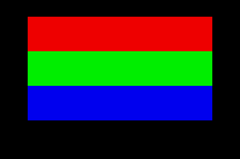
Oh, naughty me, I added a bunch of stuff to my initlib without telling you about it. Well, right
now, you’ll just have to accept it, any problems with that private!? The thing it does is to save
all information regarding resolution, screen setup and so on, then change to low resolution.
When the restore subroutine is called, it restores everything as it was. While time goes by, I
probably won’t dump all my source code into my tutorials, for example, an include initlib.s will
probably be the way in the future. I’m also thinking about sticking to just give out the
separate .s file with the source code, and only comment it here in the main tutorial so you
won’t have the same code in two places. How does that sound? You curious types can go
through the initlib code, and try to figure it out, I have commented it quite well just so you
can do that.
There might be some problems with the math here, in the clear routine, 8000 is given as the screen size. Yes, 8000 longwords, 8000×4 = 32000 bytes. 1199, or rather 1200 should equal 60 scan lines? Yes, every pass through the fill-loop moves 4 words. 4 words contain information for 16 pixels, meaning that for every loop, 16 pixels will be set. 320×60=19200 pixels total (320 pixels per scan line), and since we set 16 pixels per loop, we divide this value by 16 to get the total number of loops, which, incidentally, is 1200. That should clear any trouble with the numbers.
I hope there’s no trouble with the main loop part, the first little loop is all about making 25 VBLs, in other words, waiting for 0.5 seconds. Then, the colour values are changed, making the colours 1,2 and 3 go towards black. Lastly, another loop controller that makes sure the main loop is looped through seven times.
Now that you are equipped with basic knowledge of the graphics memory, I think we’ll be able to handle a scroller in the next part. It depends, I’ll have to write one and see if it’s not too complex. If it is too complex, you’ll probably be looking at a theory tutorial again.